
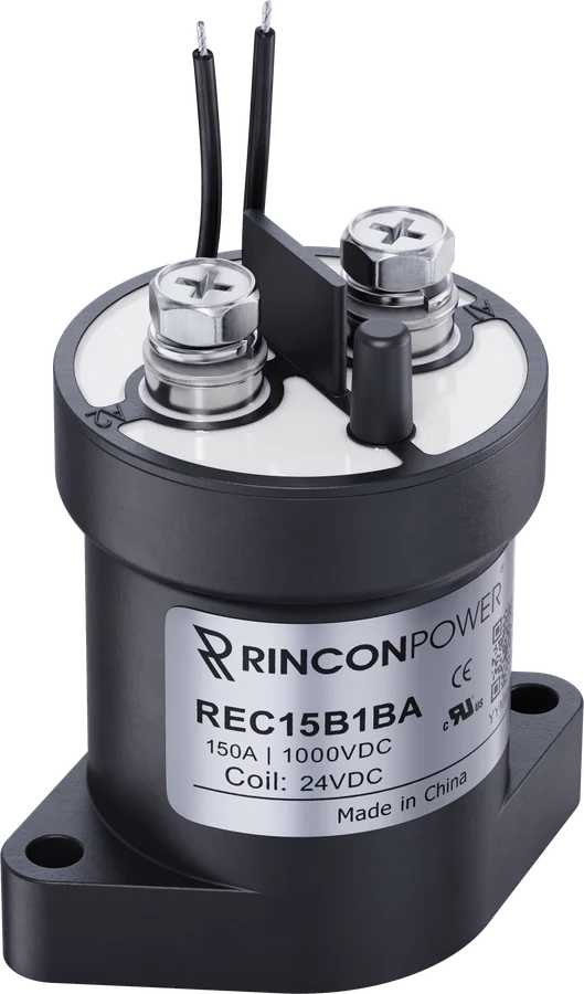
High Voltage Contactors
REC15 Series
The REC15 Series are epoxy-sealed high voltage DC contactors designed for compact, cost-effective DC power switching applications. Rated for continuous currents up to 150 A and system voltages up to 1,000 VDC, the REC15 Series delivers dependable DC switching performance in a widely adopted cylindrical form factor. Available with bi-directional main contacts and optional SPST-NO auxiliary contacts for position feedback, the REC15 Series contactors are suitable for production OEM applications where balanced performance and value are prioritized. The epoxy-sealed construction provides reliable protection for standard operating environments, making the REC15 Series an effective solution for battery power subsystems, industrial DC switching, and auxiliary power control.
Watch the 1-minute video- Continuous duty
- 150 A
- System voltage
- 1,000 VDC
- Mechanical life
- 500,000 cycles
- Dielectric withstand
- 4,000 VDC
Features and applications
REC15 at a glance
Features
- Epoxy-sealed construction for reliable DC switching
- Compact cylindrical contactor form factor
- Bi-directional DC power switching
- Optional SPST-NO auxiliary contact for main position feedback
- Single-coil operation with multiple coil voltage options (12 V, 24 V, 48 V)
- RoHS 2011/65/EU and REACH compliant
- CE Certified
- UL 60947-4-1 recognized
Typical applications
- Electric vehicle power subsystems
- Industrial equipment and machinery
- DC charging infrastructure subsystems
- Material handling and utilities
- Auxiliary DC power control and switching
- Automation and robotics power circuits
- Renewable energy power systems
- AGV Automated Guided Vehicles
Datasheet
Graphs, dimensions, drawings and installation notes are in the REC15 datasheet (Rev B).
Download datasheetDatasheet specifications
REC15 performance
| Contact Arrangement | Form X, SPST NO |
|---|---|
| Max Switching Voltage | 1,000 VDC |
| Dielectric Withstand Voltage Contacts to Coil | 4,000 VDC, 1 minute |
| Dielectric Withstand Voltage Across Open Contacts | 4,000 VDC, 1 minute |
| Continuous Current - 35 mm² conductor | 150 A |
| Continuous Current - 6 AWG, 13.3 mm² | 100 A |
| Overload Current 30 seconds | 500 A |
| Overload Current 3 Minutes | 200 A |
| Make and Break | See Table 2 |
| Max Short Circuit Current (1 second) | 1,250 A |
| Min Insulation Resistance | 1,000 MΩ @ 1,000 VDC |
| Contact Resistance (Max) | 0.4 mΩ @ 100 A | (0.25 mΩ typical) |
| Operate Time (Max, incl bounce) | 25 ms |
| Release Time (Max) | 10 ms |
| Shock - Functional, 1/2 Sine, 11 ms | 20 G |
| Shock – Destructive, 1/2 Sine, 11 ms | 50 G |
| Operating Temperature | -40°C to 85°C |
| Ingress Protection | Exceeds IP69, (Hermetically sealed) |
| Mechanical life | 500,000 |
| Contact Arrangement | SPST |
|---|---|
| Continuous Current | 2 A |
| Minimum Current | 5 mA @ 8 V |
| Coil | 12 V | 24 V | 48 V |
|---|---|---|---|
| Nominal Voltage | 12 V | 24 V | 48 V |
| Pick-up Voltage (Max) | 9.6 VDC | 19.2 VDC | 38.4 VDC |
| Drop-out Voltage (Min) | 0.8 VDC | 1.6 VDC | 3.2 VDC |
| Holding Current | 0.46 A | 0.25 A | 0.12 A |
| Coil Resistance +/- 5% | 26 Ω | 96 Ω | 392 Ω |
| Coil Power | 5.5 W | 6 W | 6 W |
| Voltage | Current | Cycles |
|---|---|---|
| Bi-Directional Version | ||
| 450 V | 100 A | 25,000 |
| 800 V | 100 A | 7,500 |
| 800 V | 50 A | 30,000 (BREAK ONLY) |
| 1,000 V | 100 A | 500 |
| 320 V | 400 A | 1 cycle / fault interrupt |
Table 2 of the REC15 datasheet, Rev B, as printed. Resistive load; 1 cycle = 1 make + 1 break.
Datasheet notes
- Bi-directional version is designed for maximum fault interrupt. As a result, no polarity sensitive version is required.
- For Bi-Directional versions the direction of current does not matter when breaking under load.
- The auxiliary contacts are connected internally via an armature on the main contact plunger. As the main contacts close, they automatically cause the auxiliary contacts to close.
- Contactor may be used above Max Switching Voltage if the application does not require significant load breaking. Please contact Rincon Power to discuss in more detail.
- Attached cables and busbars directly to the main terminal pad using the recommended install torque. Do not use washers or other materials between the contactor and the conductor. This will ensure the lowest possible contact resistance.
- Avoid excessive coil voltages. Exceeding the ratings on the datasheet may result in high coil temperature and coil failure.
From the REC15 datasheet, Rev B. Download the datasheet for graphs, dimensions and installation.
Part numbers
Build your REC15 part number
Choose each option and the part number updates. Only standard part numbers from the datasheet are offered. Copy it, or request a quote for that exact part.
Options and part numbers from the REC15 datasheet. Other combinations may be available as custom builds.
All standard REC15 part numbers
Request a quote
Get pricing for the REC15 Series
Tell us the part number if you have one, and how many you need. An application engineer will reply with pricing and lead time.
Prefer to talk? Call +1 805 456 6424 or email [email protected].
Thanks, we have your request
An application engineer will reply with pricing and lead time.
Need it sooner? Call +1 805 456 6424 or email [email protected].
Product video
The REC15 Series in one minute
Related contactors
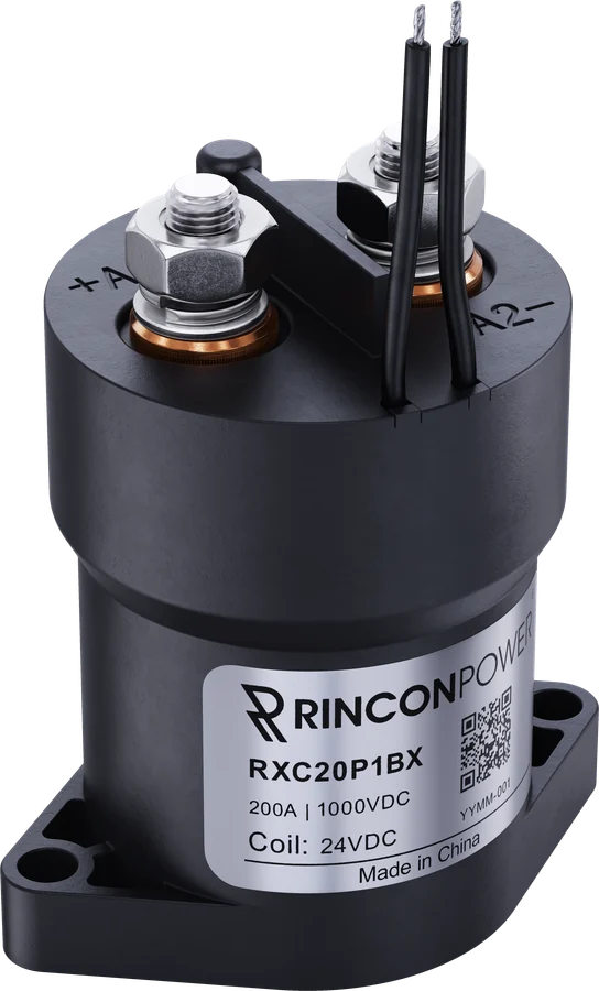
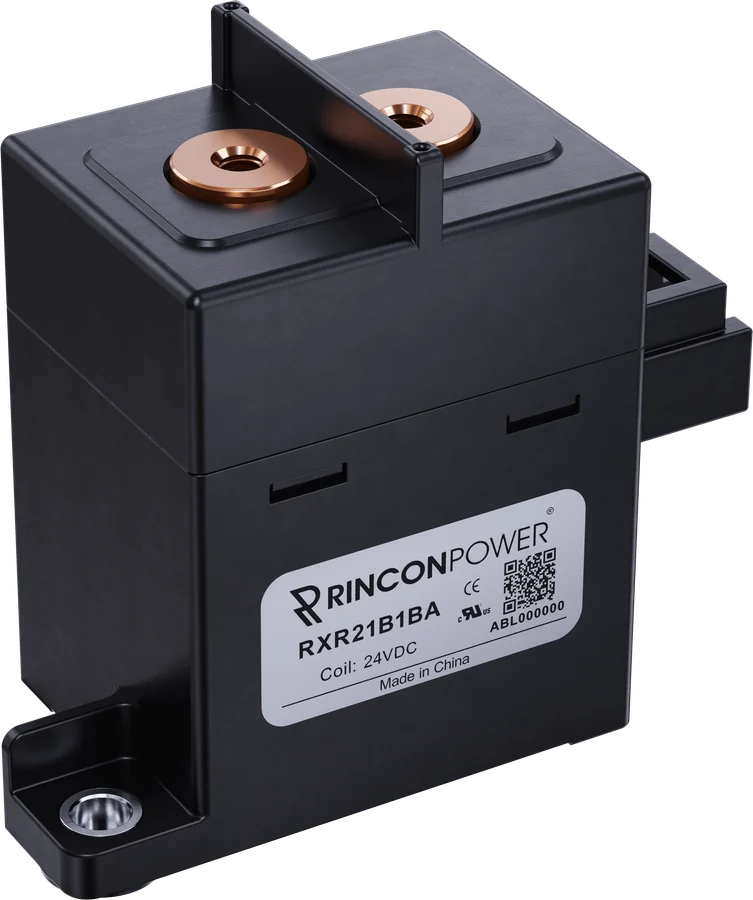
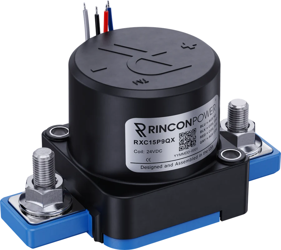
Compare similar series
Questions about the REC15 Series?
Talk to an application engineer about ratings, options or a custom build.