
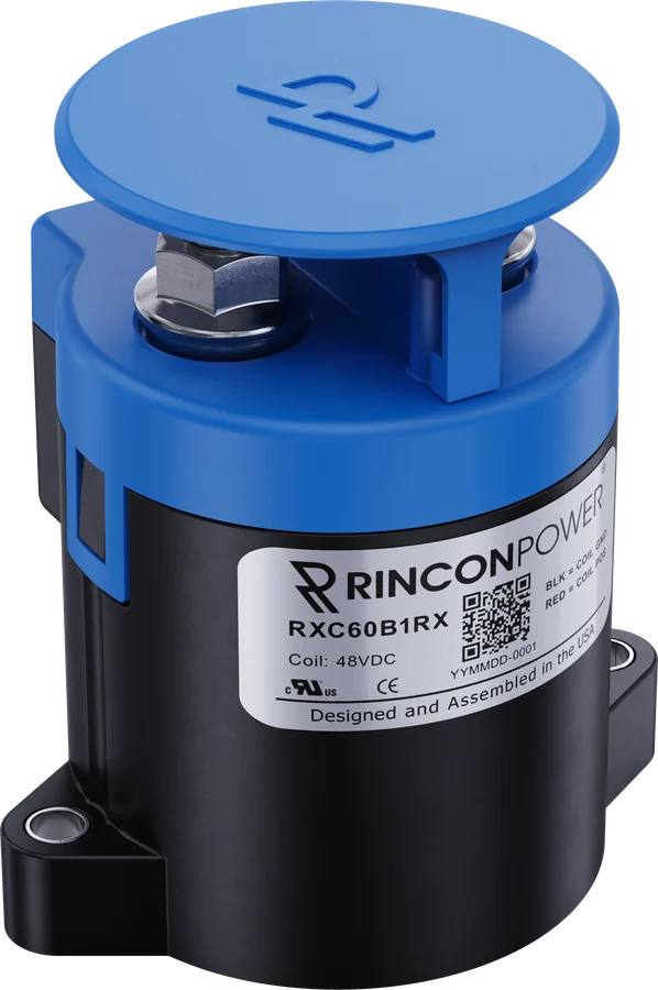
High Voltage Contactors
RXC60 Series
The RXC60 Series are hermetically sealed high voltage DC contactors designed for high-current power switching in demanding applications. Rated for continuous currents up to 600 A and system voltages up to 1,000 VDC, the RXC60 Series features bi-directional switching, integrated coil economization, and mechanically linked auxiliary contacts for reliable position feedback. Designed and assembled in the USA, these contactors are ideal for energy storage systems, electric vehicle battery systems, charging infrastructure, AI data center backup power systems, humanoid robotics, AGV’s, and industrial DC power control.
Watch the 1-minute video- Continuous duty
- 600 A
- System voltage
- 1,000 VDC
- Mechanical life
- 300,000 cycles
- Dielectric withstand
- 2,200 VRMS
Features and applications
RXC60 at a glance
Features
- Hermetic Ceramic Seal with gas fill for superior carry and switching performance
- Bi-Directional Power Switching
- Mechanically linked auxiliary contacts for accurate main position feedback
- Integrated coil economizer for optimized power consumption
- Integrated coil suppression with zero back-EMF
- Meets RoHS 2011/65/EU
- UL 60947-4-1 recognized (File E536262)
- Patent Pending
- Designed and Assembled in the USA
Typical applications
- Battery Energy Storage Systems (BESS)
- Electric and off-highway vehicles
- DC fast charging infrastructure
- AI data center backup power systems
- Humanoid and industrial robotics platforms
- Solar DC power distribution and control
- Industrial machinery and equipment
- Heavy trucks, buses, mining and construction vehicles
- AGV Automated Guided Vehicles
Datasheet
Graphs, dimensions, drawings and installation notes are in the RXC60 datasheet (Rev C).
Download datasheetDatasheet specifications
RXC60 performance
| Contact Arrangement | Form X, SPST- NO |
|---|---|
| Max Switching Voltage | 1,000 VDC |
| Dielectric Withstand Voltage (Leakage <1 mA) Between Open Contacts | 2,200 VRMS (60 sec) |
| Between Contacts and Coil | 2,200 VRMS (60 sec) |
| Mechanical Life | 300,000 cycles |
| Continuous Current (using 300 mm² conductor) | 600 A |
| Overload Current | See Momentary Current Carry graph |
| Max Current Withstand | 4,000 A, 20 ms |
| Make and Break | See Estimated DC Power Switching Cycles graph |
| Min Insulation Resistance | 100 MΩ @ 1,000 V (50 MΩ at end of life) |
| Contact Resistance (Max) measured at 200 A | 0.3 mΩ |
| (Typical) measured at 200 A | 0.1-.15 mΩ |
| Operate Time (Max, incl bounce) | 25 ms |
| Release Time (Max) | 10 ms |
| Shock - Functional, 1/2 Sine, 11 ms | 20 G Peak |
| Shock - Destructive, 1/2 Sine, 11 ms | 50 G Peak |
| Vibration, Sinusoidal (500-2,000 Hz Peak) | 15 G |
| Operating Temperature | -40°C to 85°C (170°C max terminal temperature) |
| Sealed Contacts | Exceeds IP69K (hermetically sealed) |
| Salt Fog | MIL-STD-810 |
| Contact Arrangement Options | Form A, SPST - Normally Open Form B, SPST - Normally Closed Form C, SPDT - Normally Open & Normally Closed |
|---|---|
| Continuous Current | 3 A / 24 VDC |
| Minimum Current | 1 mA @ 5 V |
| Coil | 12 V | 24 V | 48 V |
|---|---|---|---|
| Nominal Voltage | 12 V | 24 V | 48 V |
| Max Voltage | 16 V | 32 V | 64 V |
| Pick-up Voltage | ≥9 V | ≥18 V | ≥36 V |
| Drop-out Voltage | ≤6 V | ≤12 V | ≤24 V |
| Inrush Current, Max (80 ms) | 3.8 A | 1.9 A | 0.9 A |
| Coil Current | 0.65 A | 0.33 A | 0.16 A |
| Coil Power | 7.8 W | 7.8 W | 7.8 W |
Datasheet notes
- Integrated coil suppression limits back-EMF to 0 V. External diodes or suppressors do not affect operation.
- Contactor may be used above Max Switching Voltage if the application does not require significant load breaking. Please contact Rincon Power for more details.
- Attach cables and busbars directly to the main terminal pad using the recommended install torque. Do not use washers or other materials between the contactor power terminals and the conductor.
- Dual coil economizer design: Pickup Voltage must be applied as a pulse. Do not ramp voltage.
- Rigid busbar structures have the potential to induce stress into the device and can damage the hermetic seal. When using busbars, it is important to design compliance into the bus bar structure via the use of flexible laminated busbars and or by means of incorporating adjustability in adjacent bolted interfaces.
From the RXC60 datasheet, Rev C. Download the datasheet for graphs, dimensions and installation.
Part numbers
Build your RXC60 part number
Choose each option and the part number updates. Only standard part numbers from the datasheet are offered. Copy it, or request a quote for that exact part.
Options and part numbers from the RXC60 datasheet. Other combinations may be available as custom builds.
All standard RXC60 part numbers
- RXC60B1PA
- RXC60B1PB
- RXC60B1PC
- RXC60B1PX
- RXC60B1QA
- RXC60B1QB
- RXC60B1QC
- RXC60B1QX
- RXC60B1RA
- RXC60B1RB
- RXC60B1RC
- RXC60B1RX
- RXC60B8PA
- RXC60B8PB
- RXC60B8PC
- RXC60B8PX
- RXC60B8QA
- RXC60B8QB
- RXC60B8QC
- RXC60B8QX
- RXC60B8RA
- RXC60B8RB
- RXC60B8RC
- RXC60B8RX
- RXC60B9PA
- RXC60B9PB
- RXC60B9PC
- RXC60B9PX
- RXC60B9QA
- RXC60B9QB
- RXC60B9QC
- RXC60B9QX
- RXC60B9RA
- RXC60B9RB
- RXC60B9RC
- RXC60B9RX
Request a quote
Get pricing for the RXC60 Series
Tell us the part number if you have one, and how many you need. An application engineer will reply with pricing and lead time.
Prefer to talk? Call +1 805 456 6424 or email [email protected].
Thanks, we have your request
An application engineer will reply with pricing and lead time.
Need it sooner? Call +1 805 456 6424 or email [email protected].
Product video
The RXC60 Series in one minute
Related contactors
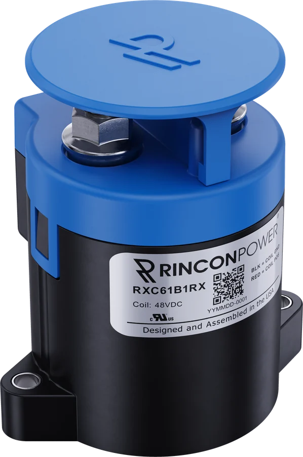
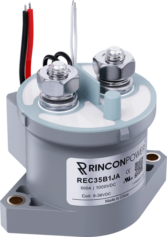
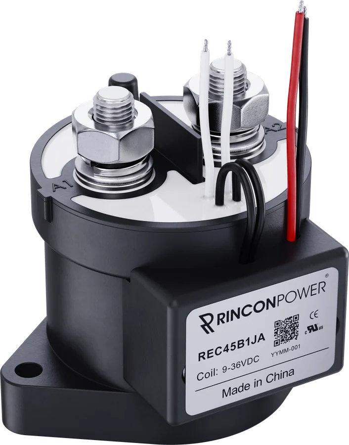
Compare similar series
Questions about the RXC60 Series?
Talk to an application engineer about ratings, options or a custom build.